By Tom Eklöf (obrotund on Discord), 2021 (CC BY-SA 4.0 license.)
Previous post on RKS: https://blackbag.toool.nl/?p=3416
This is a proof of concept for a manipulation method for the RKS. At least a passing familiarity with safe combination lock manipulation is assumed.
As far as I know this is the first public manipulation for the RKS – or at least it was when I did the actual manipulation some months before writing this post. Please do let me know if you know of others before me.
editors note: Pics or it didn’t happen, no hearsay allowed. 🙂
RKS operating principle
I’ll provide a quick rundown of how the RKS lock works, but I’d suggest reading Han Fey’s excellent writeup for more in-depth information. Note that there are some differences between what’s detailed in the doc versus the lock I have, but the general idea is the same.
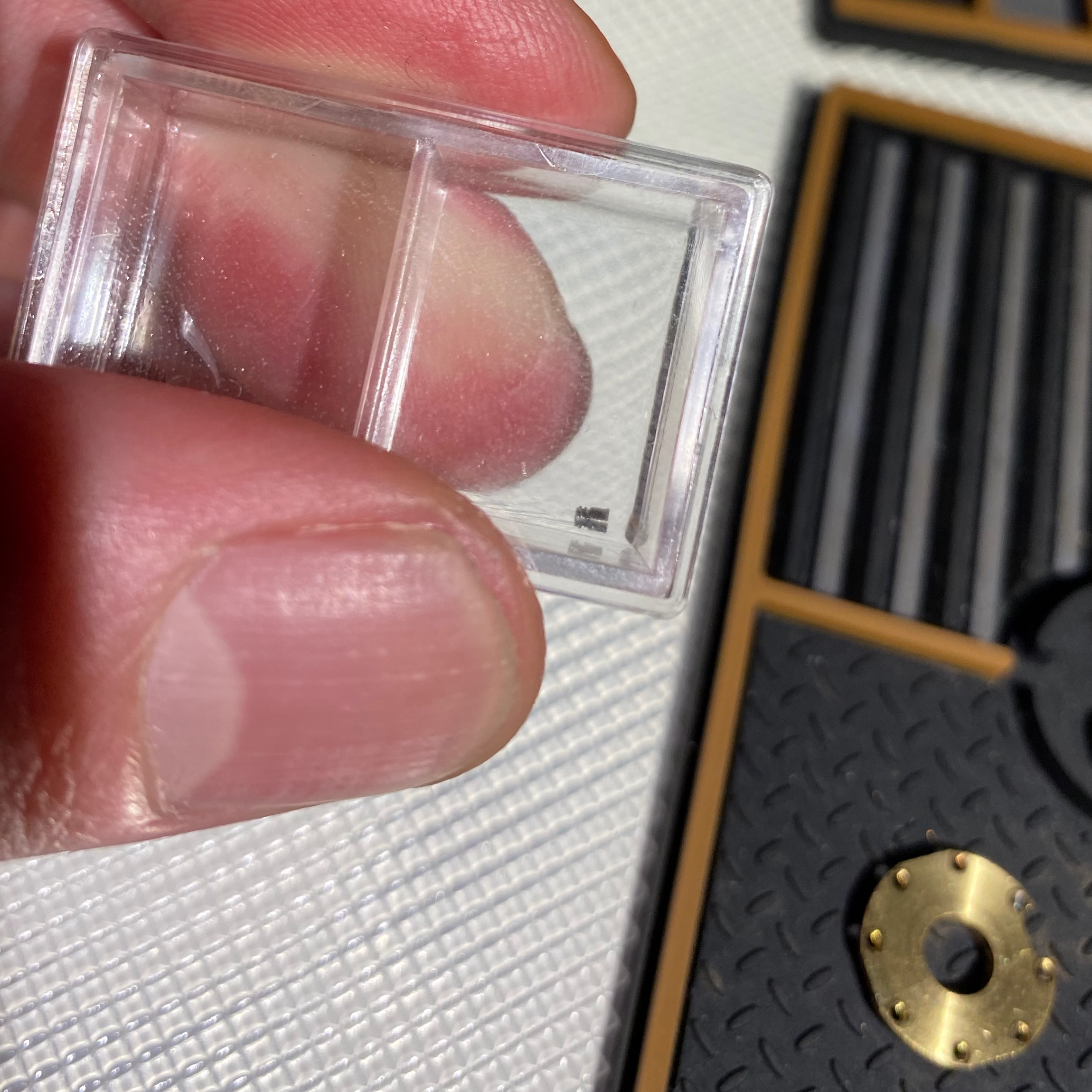
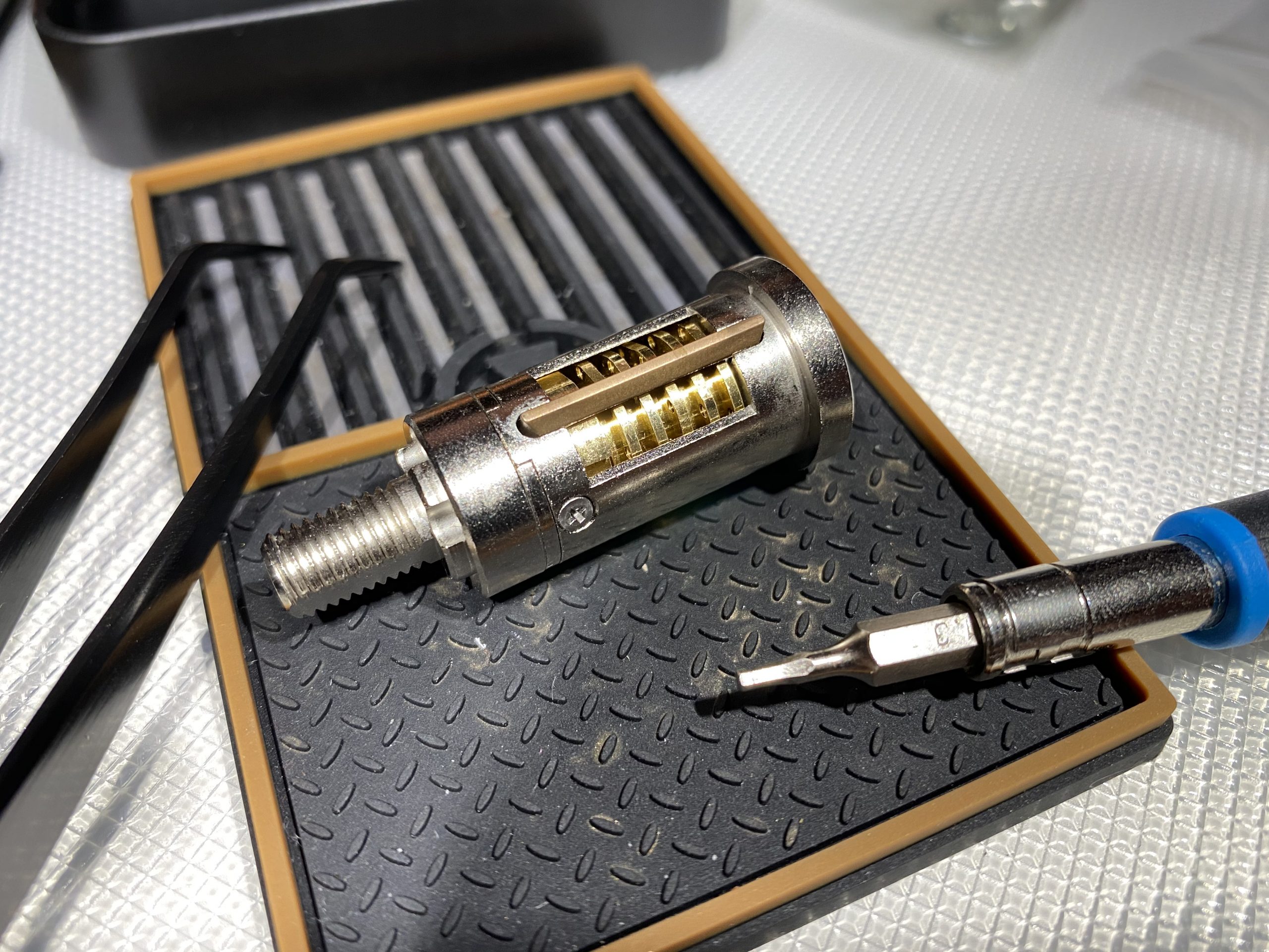
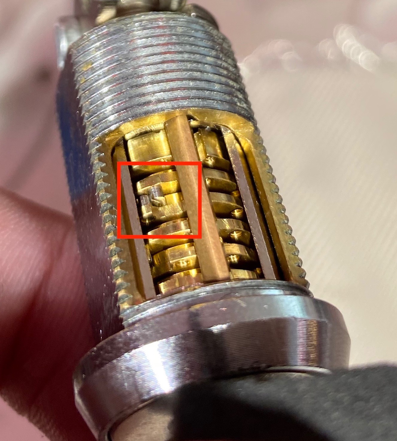
The RKS cam lock innards resemble a hybrid of a fixed drive pin combination lock and a disk detainer lock. Like both disk detainers and combination locks, it has several disks with gates on them (ie. wheels in combination lock terms, but the RKS doc uses “disk” so I’ve stuck to the same terminology) – 5 in my version – and a drive disk which is equivalent to the cam. Like in combination locks, the gates can use the full 360° of the disk. Each disk including the drive disk has multiple false gates in addition to the true gate, but they’re equally spaced. Like in a disk detainer cam lock, the plug is prevented from rotating by a sidebar that fits into the gates on the disks. The combination is changed by changing the position of a drive pin on the edge of each disk, similarly to screw change combination locks although it seemed like only the “bottom” or dialer side pin is changeable – or possibly the ones I tried were just very tight, but I didn’t want to force them considering how tiny the screws are.
The drive disk is at the “far” or cam end of the lock, and it’s driven by a drive shaft that goes through the disk pack and is connected to a detachable dialer, either manual (which I have) or electronic. In effect this gives us a 5 wheel combination lock with each number in the combination between 0 – 63 which is opened like a fixed drive pin lock: you always track the previous number, so if the combination starts L30 R7 L28 … you need to pass L30 5 times (ie stop on the 6th), then dialing R7 you need to pass 30 4 times before stopping on R7, then going to L28 you need to pass 7 three times etc etc. After you’ve dialed the combination you apply counterclockwise tension to the edge of the dialer to rotate the plug itself (ie you don’t rotate the “dialing part” of the dial so the drive disk doesn’t move), which then forces the sidebar to slide down into the gates and allows the plug to rotate.
Note: I’ll use the same numbering scheme for the disks as with combination locks, so disk 1 (abbreviated to d1) is the one closest to the dialer and disk 5 (d5) the one furthest away from it, right next to the drive disk.
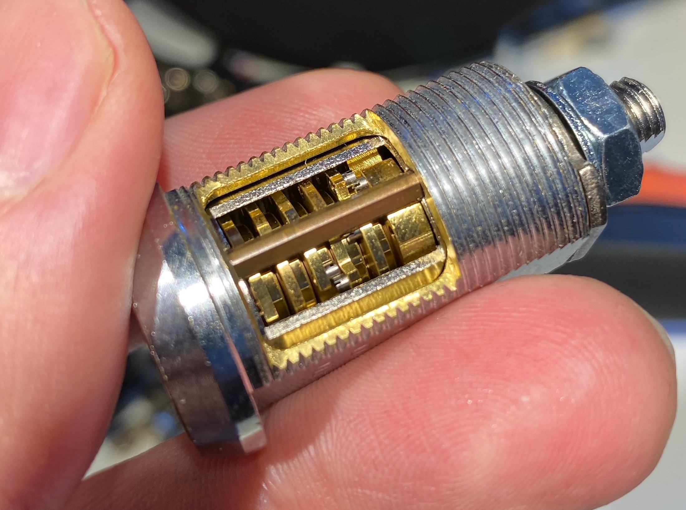
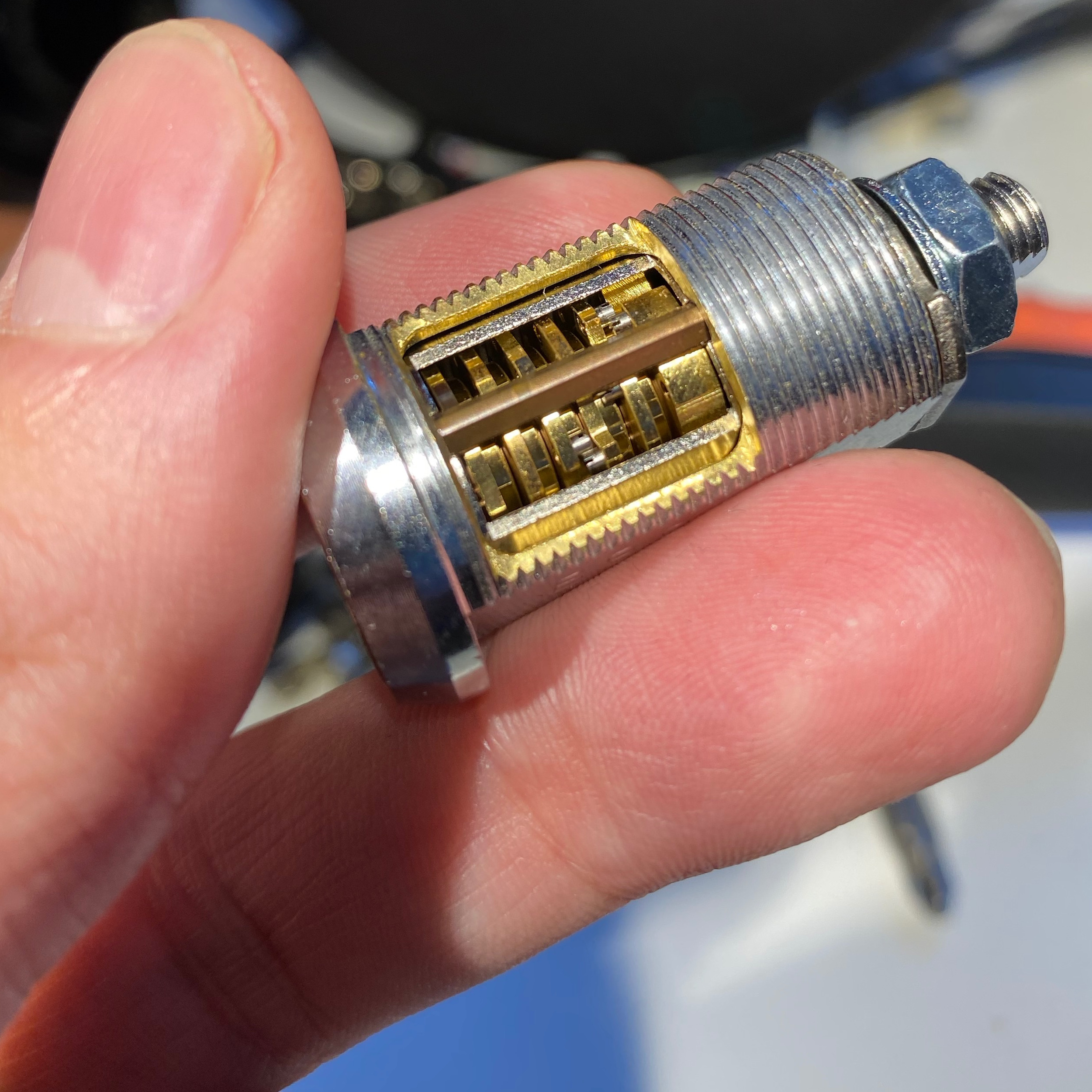
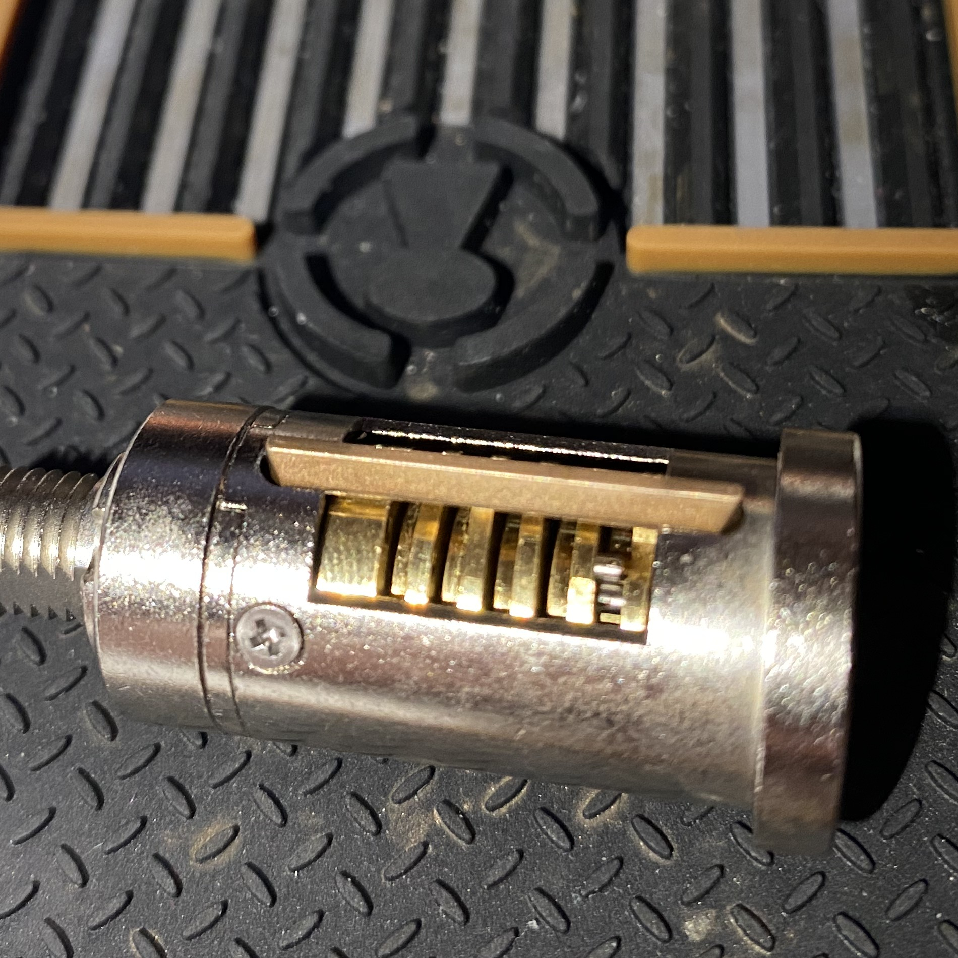
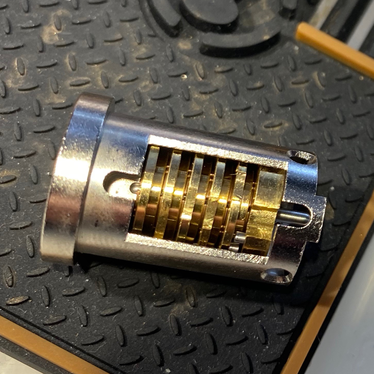
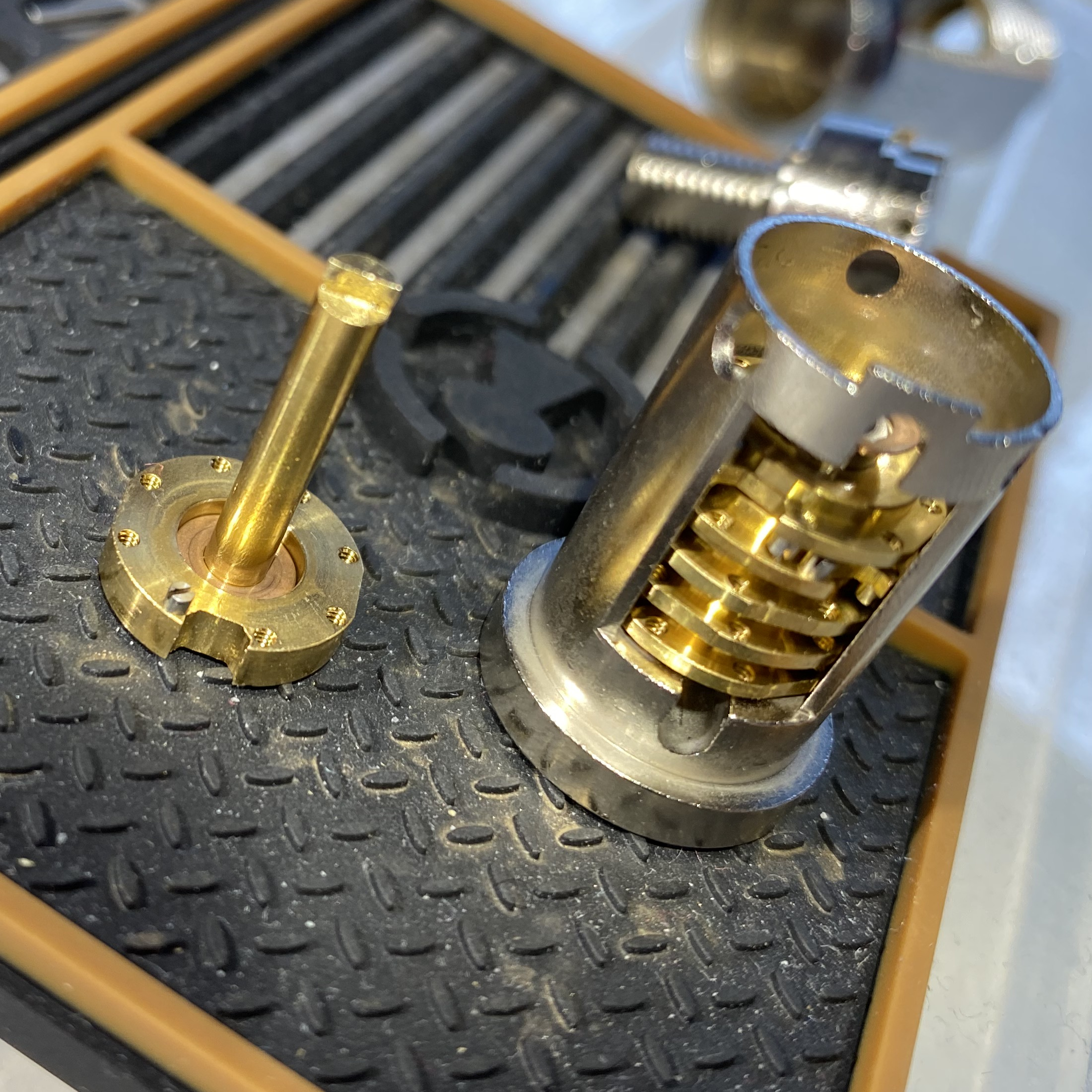
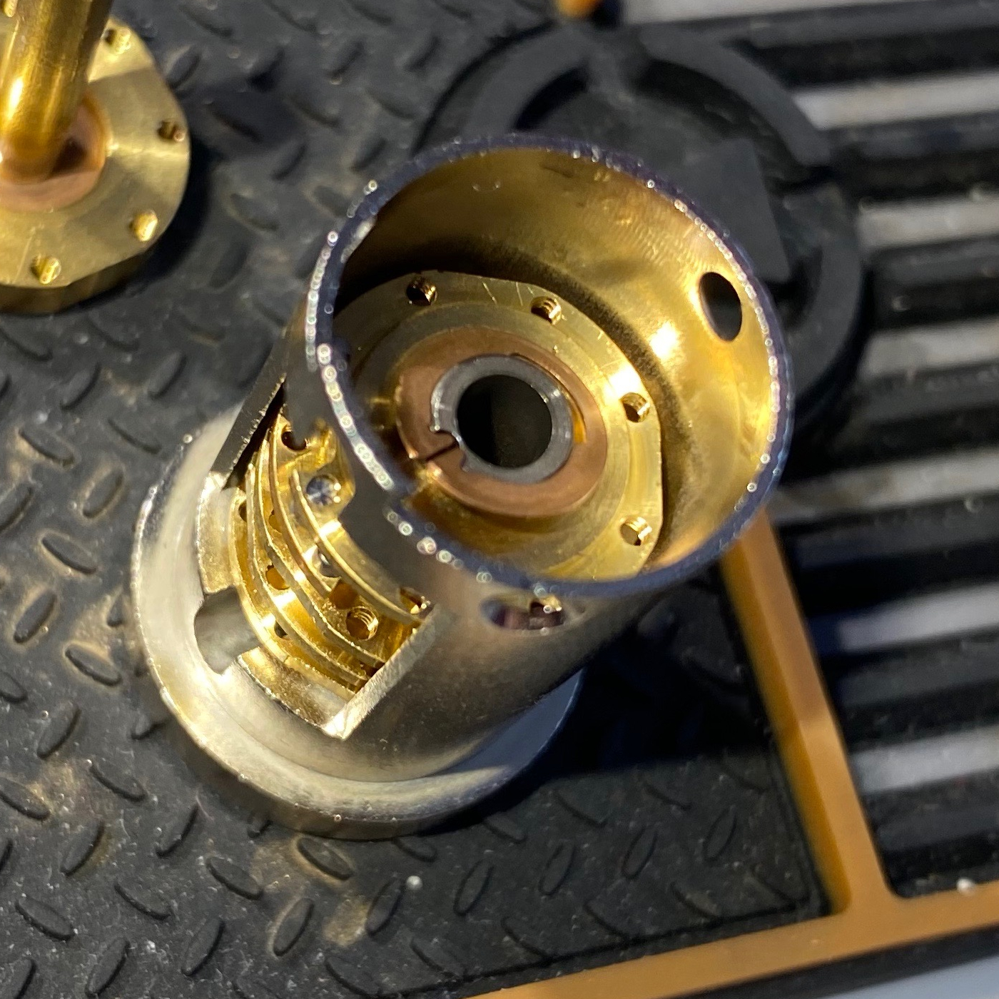
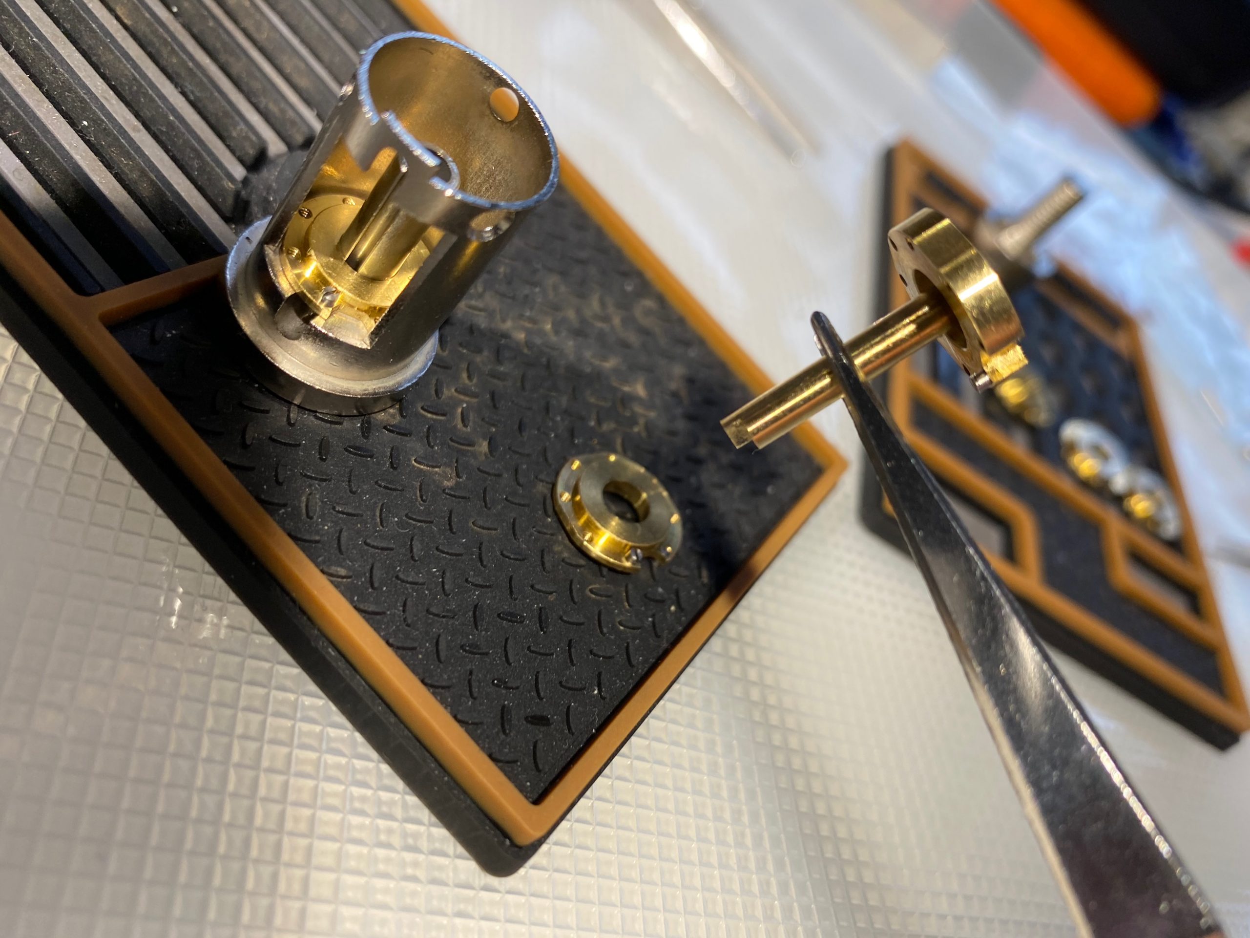
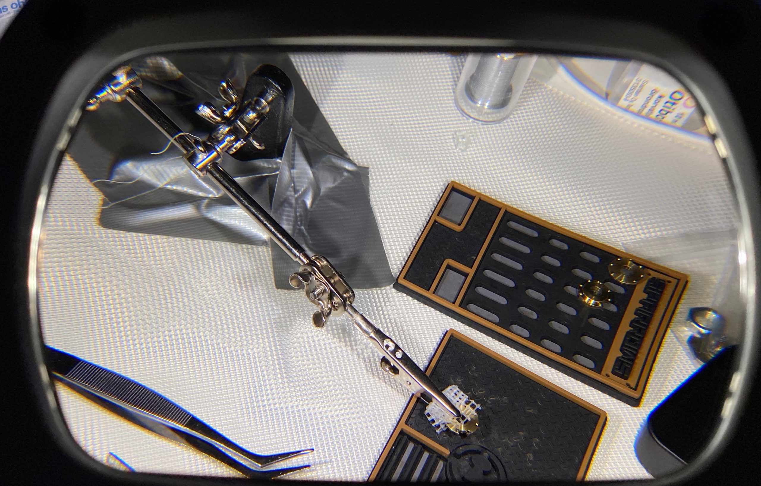
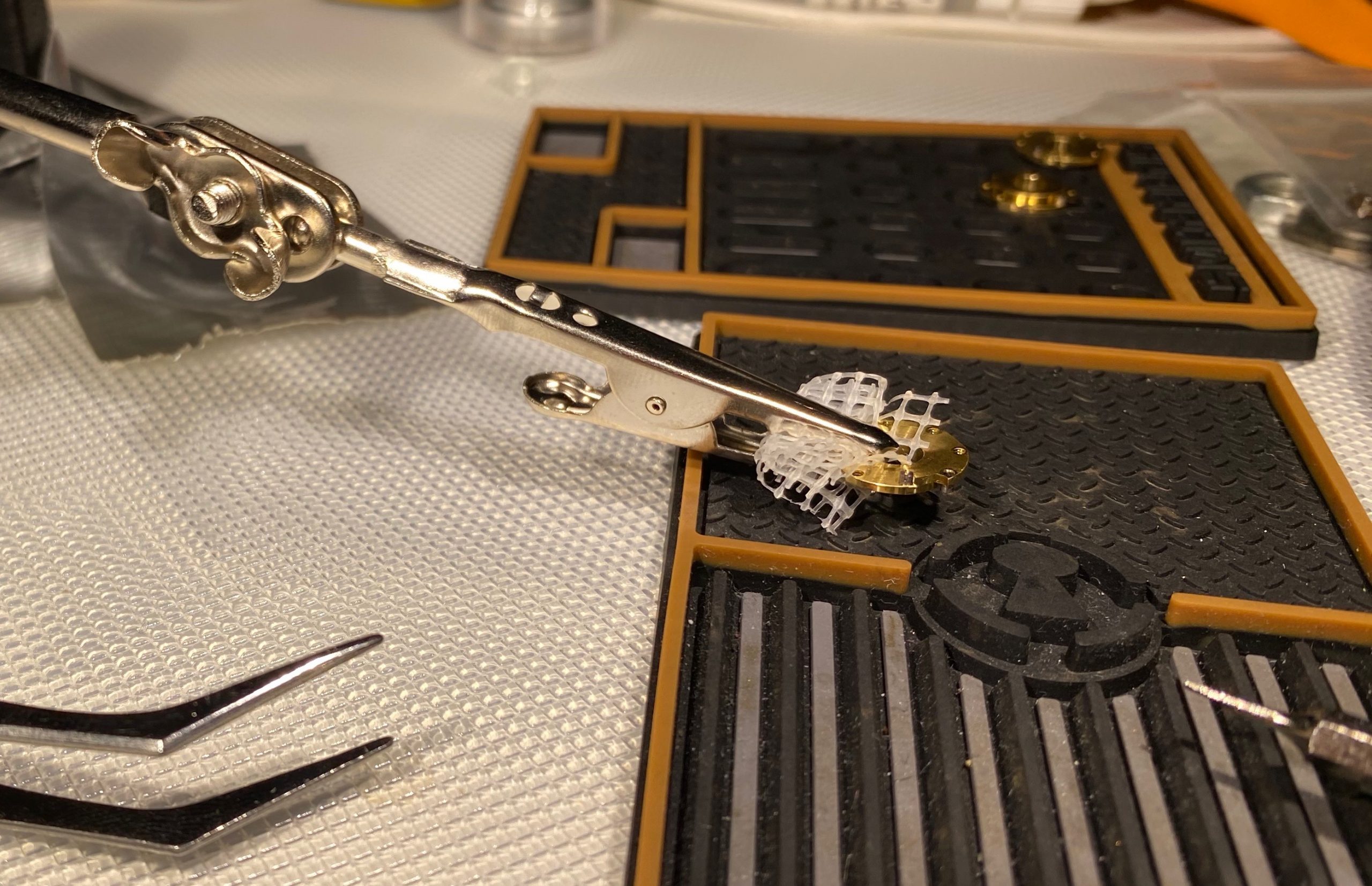
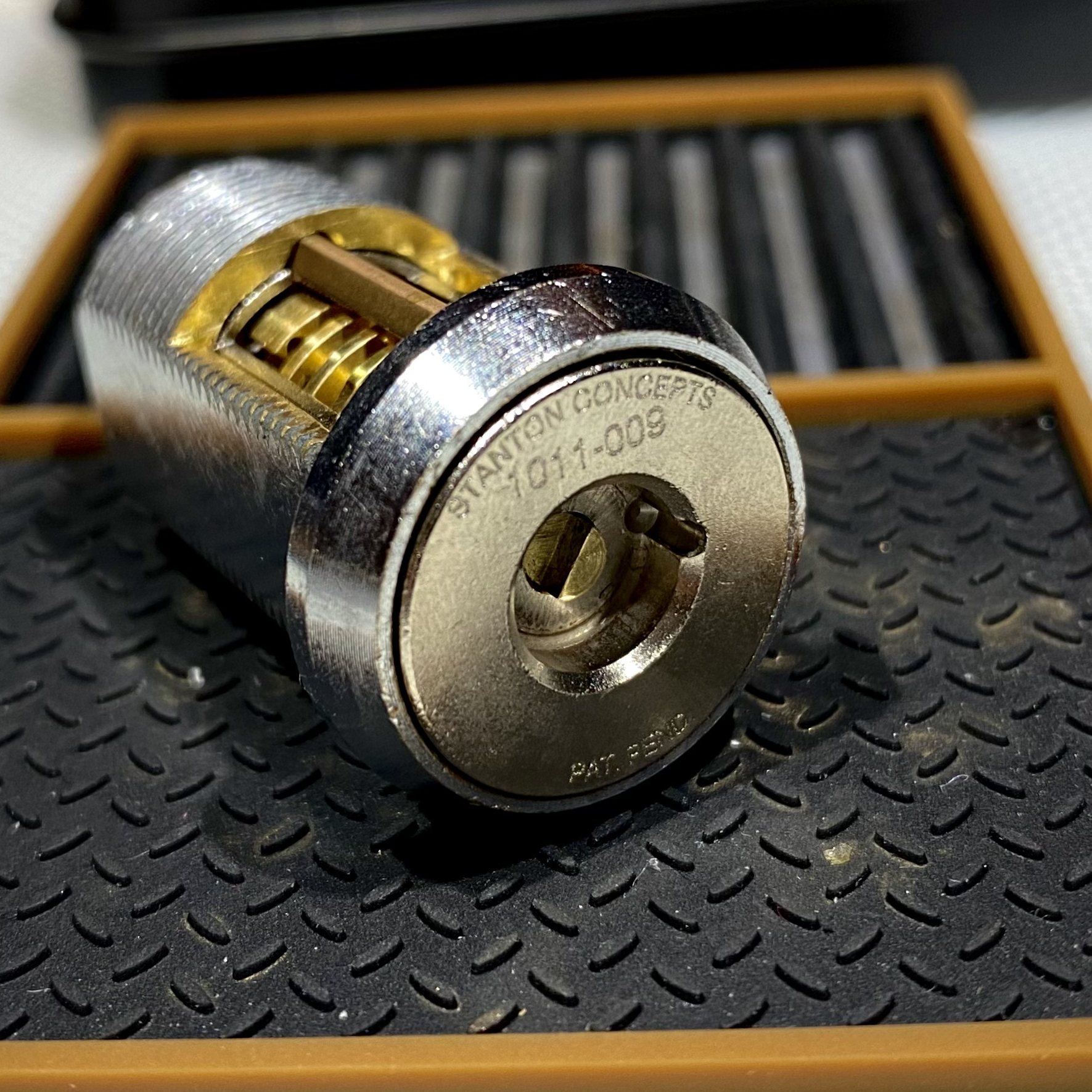
The cutaway lock, sidebar and disks visible. The drive disk is the one on the right, followed by d5, then d4 etc.
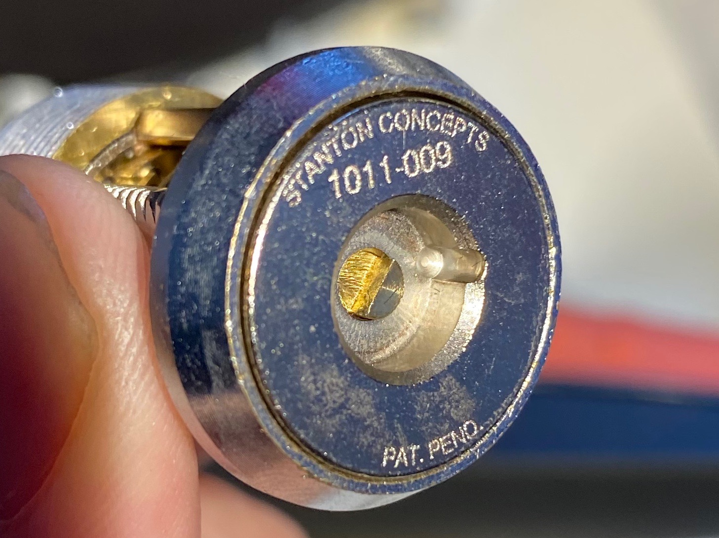
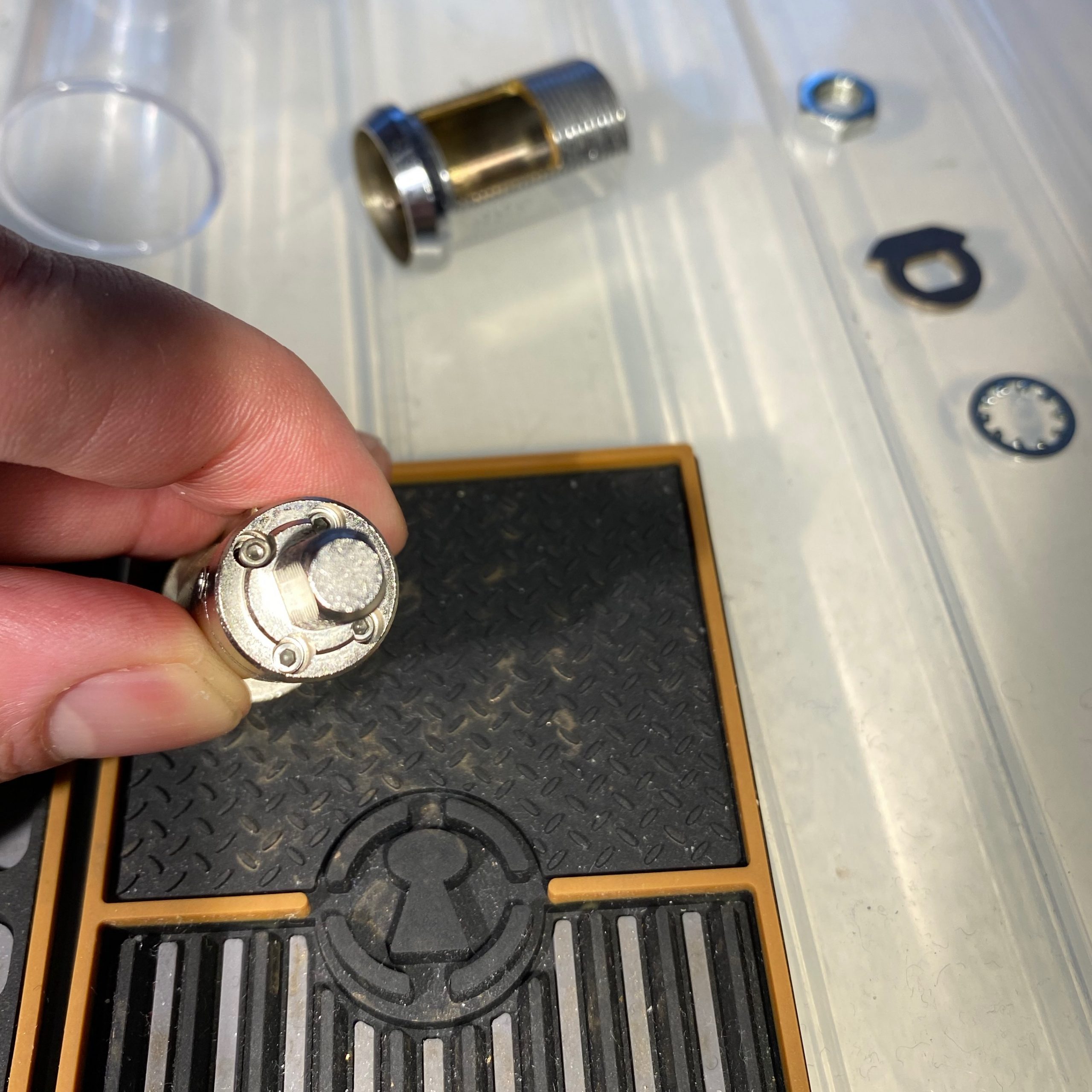
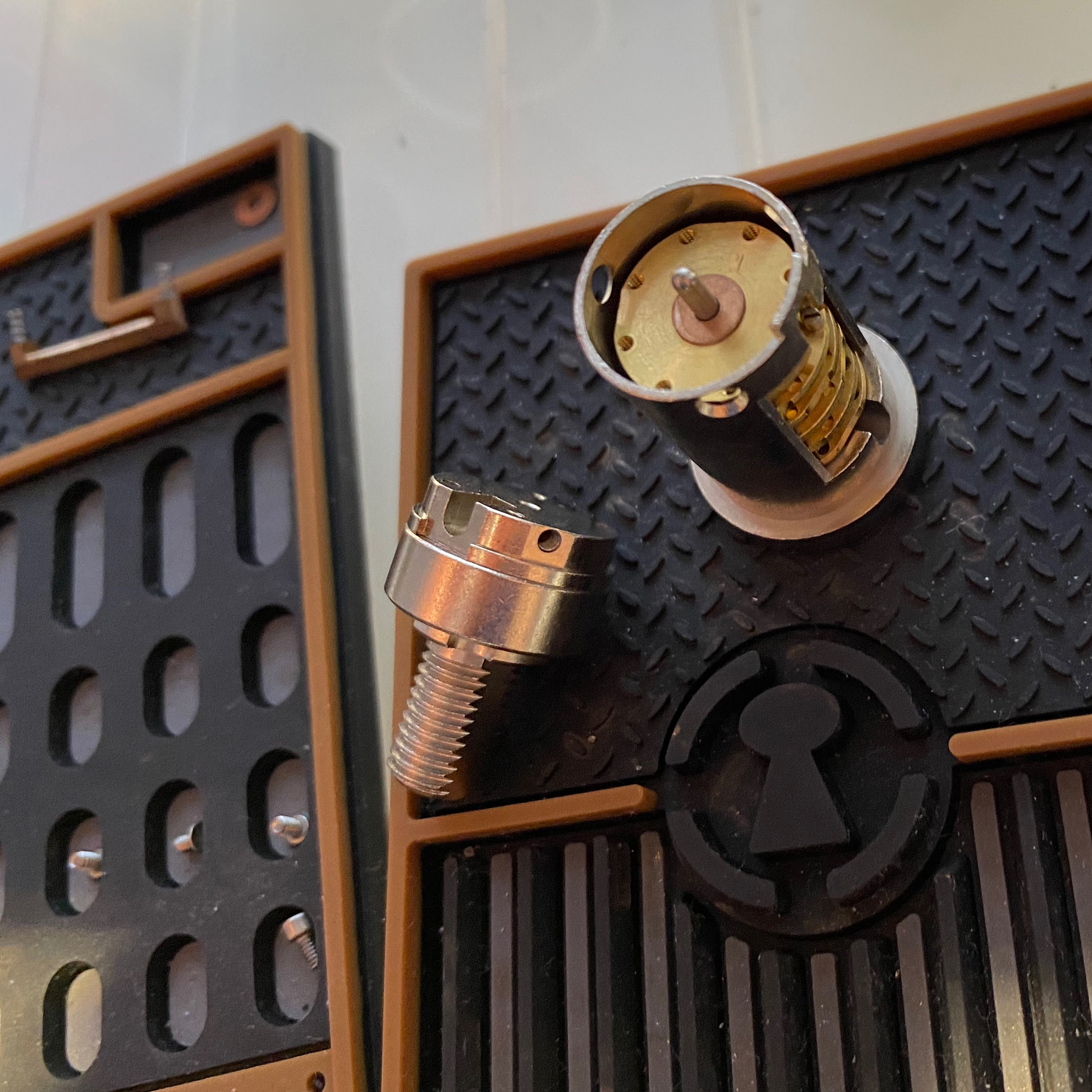
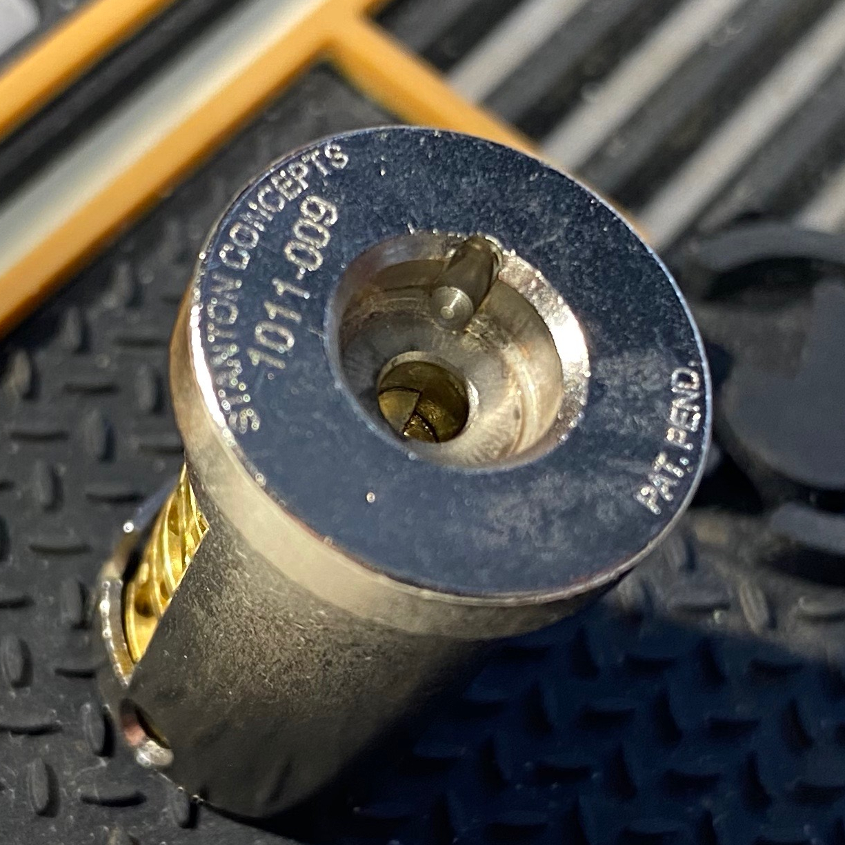
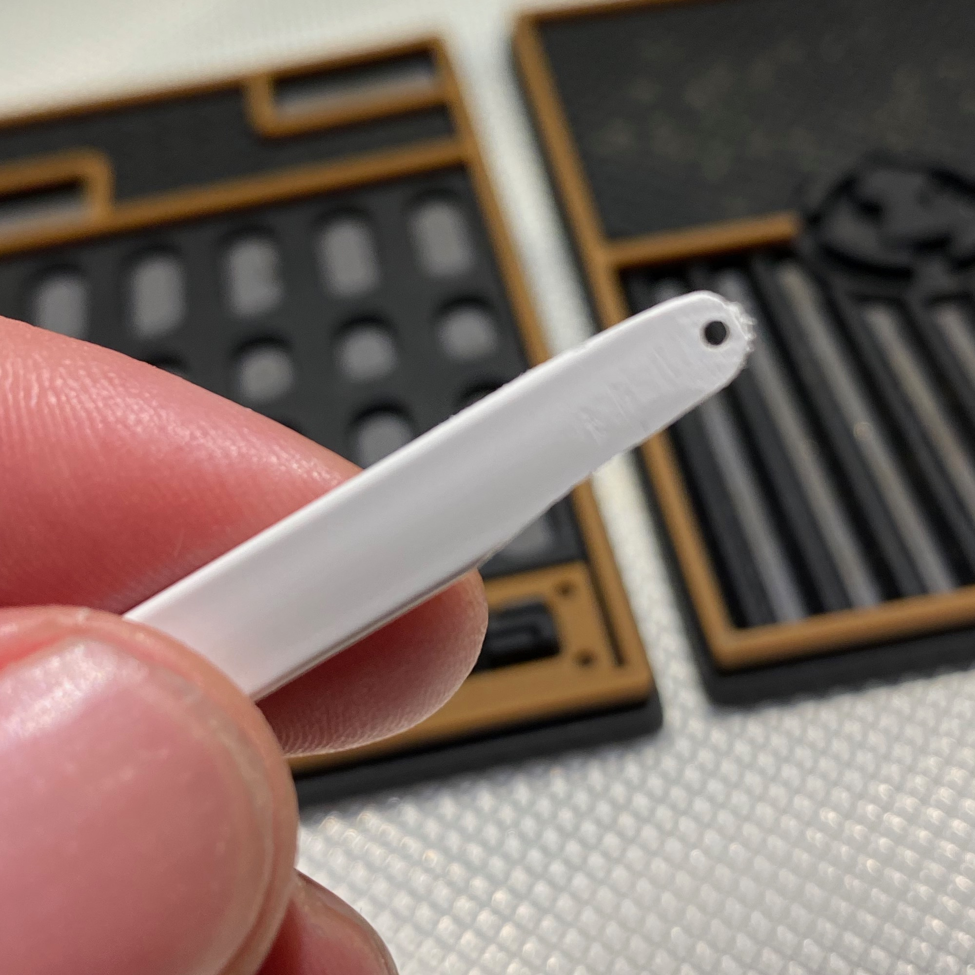
View of the “keyway”
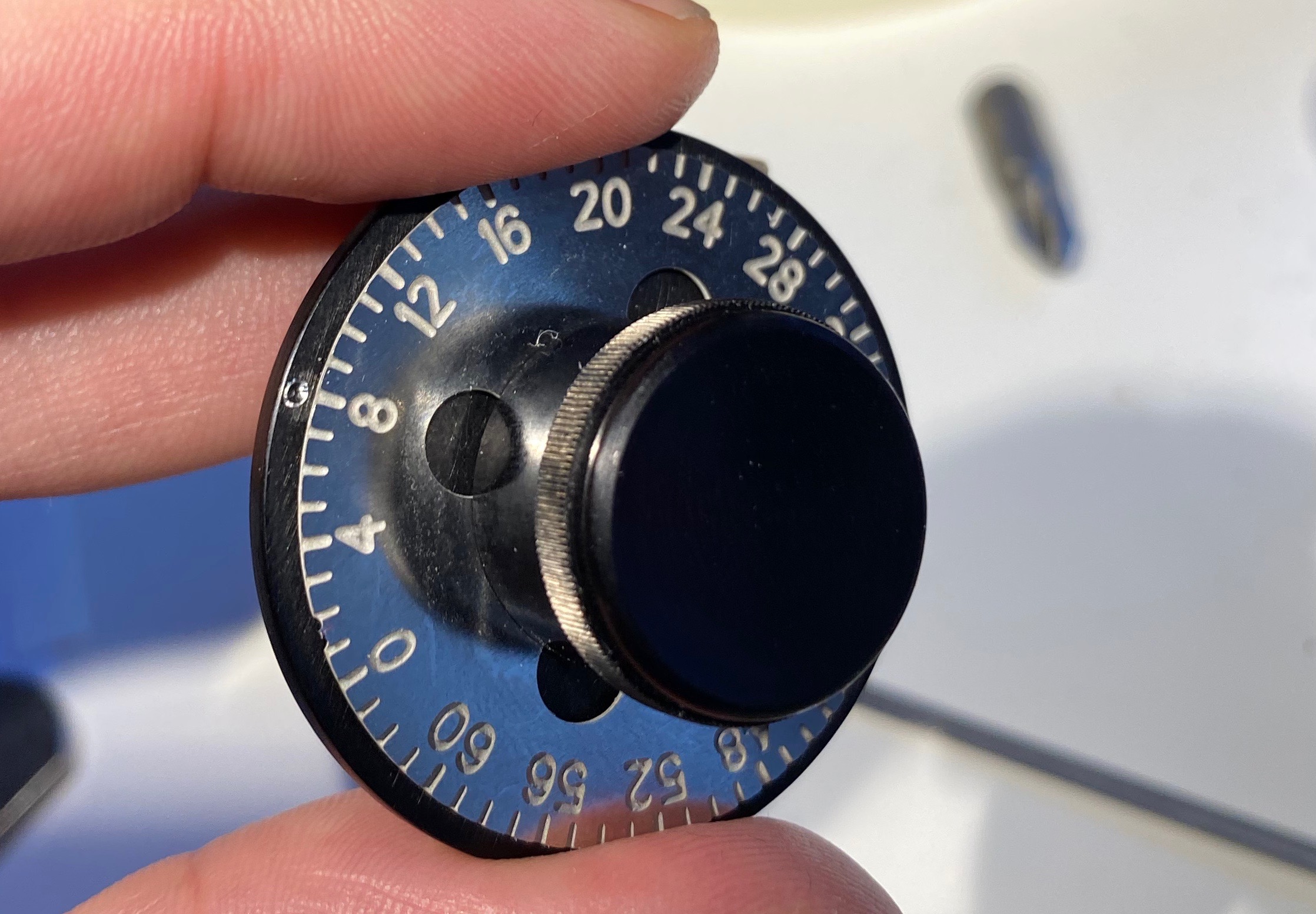
Manual dialer. The dial itself is rotated with the knob, and torquing the body / edge (the black part) of the dialer counterclockwise is used to actually open the lock
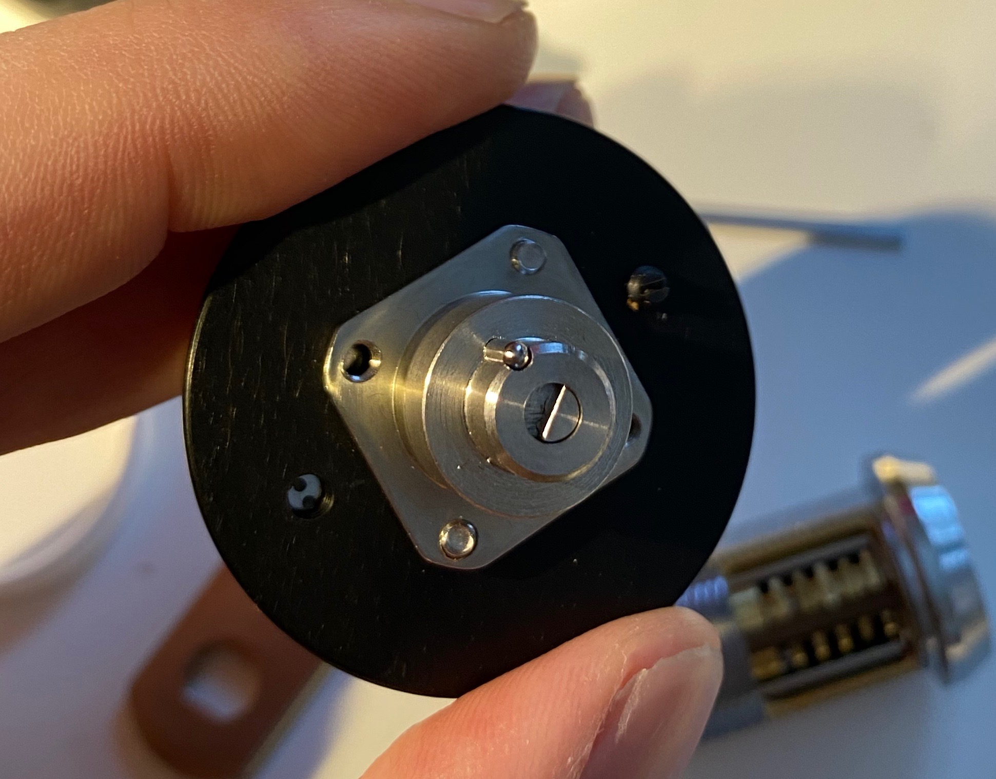
Manual dialer, underside. The black screw visible on the right side of the body of the dialer makes it click to increments when dialing
Measurements
- number range 0 – 63, meaning 5.625° per increment
- 5 disks and a drive disk
- 4 gates per disk (including drive), 3 of which false at 16 increments or 90° apart
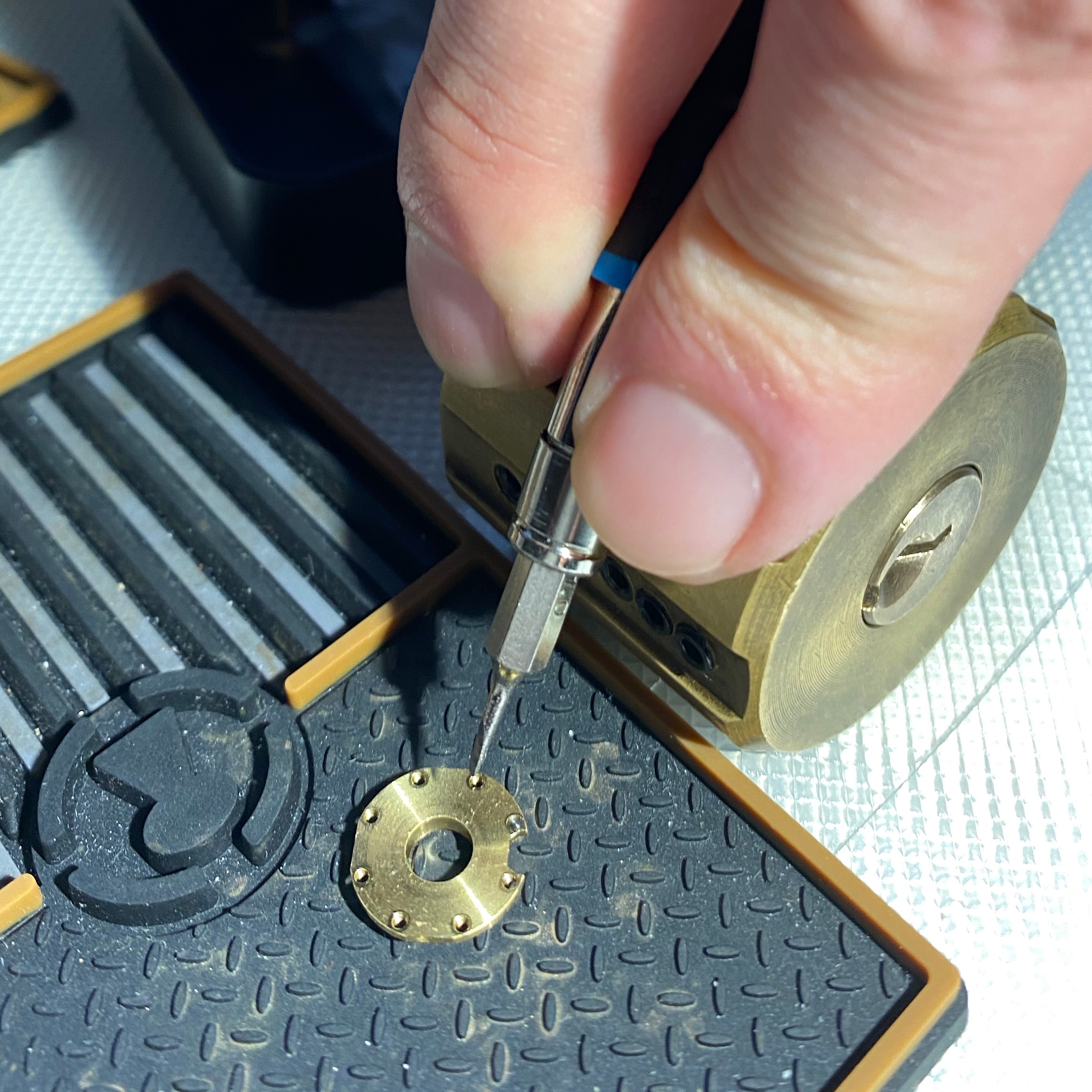
- 8 drive pin holes per disk, at both edges of each gate
- gates are ~5 (28°) increments wide, including the drive disk. Measured by looking at the cutaway from the top and moving the edge of the sidebar from one side of a gate to another
- gate binding (or, rather, lack thereof) can be felt for ~6 increments
- drive pin width is ~2 increments, 11.25°
- sidebar ~2.2mm
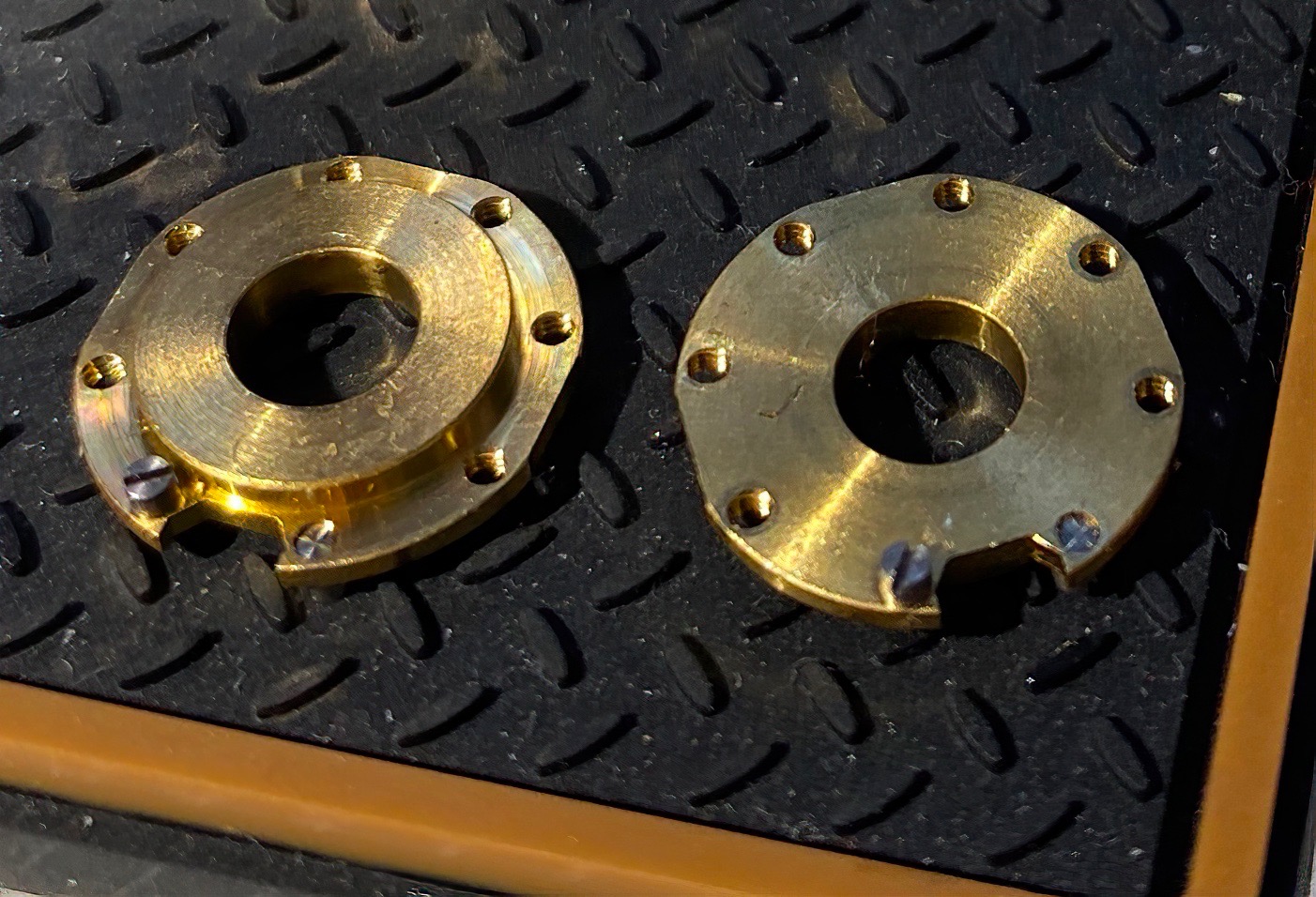
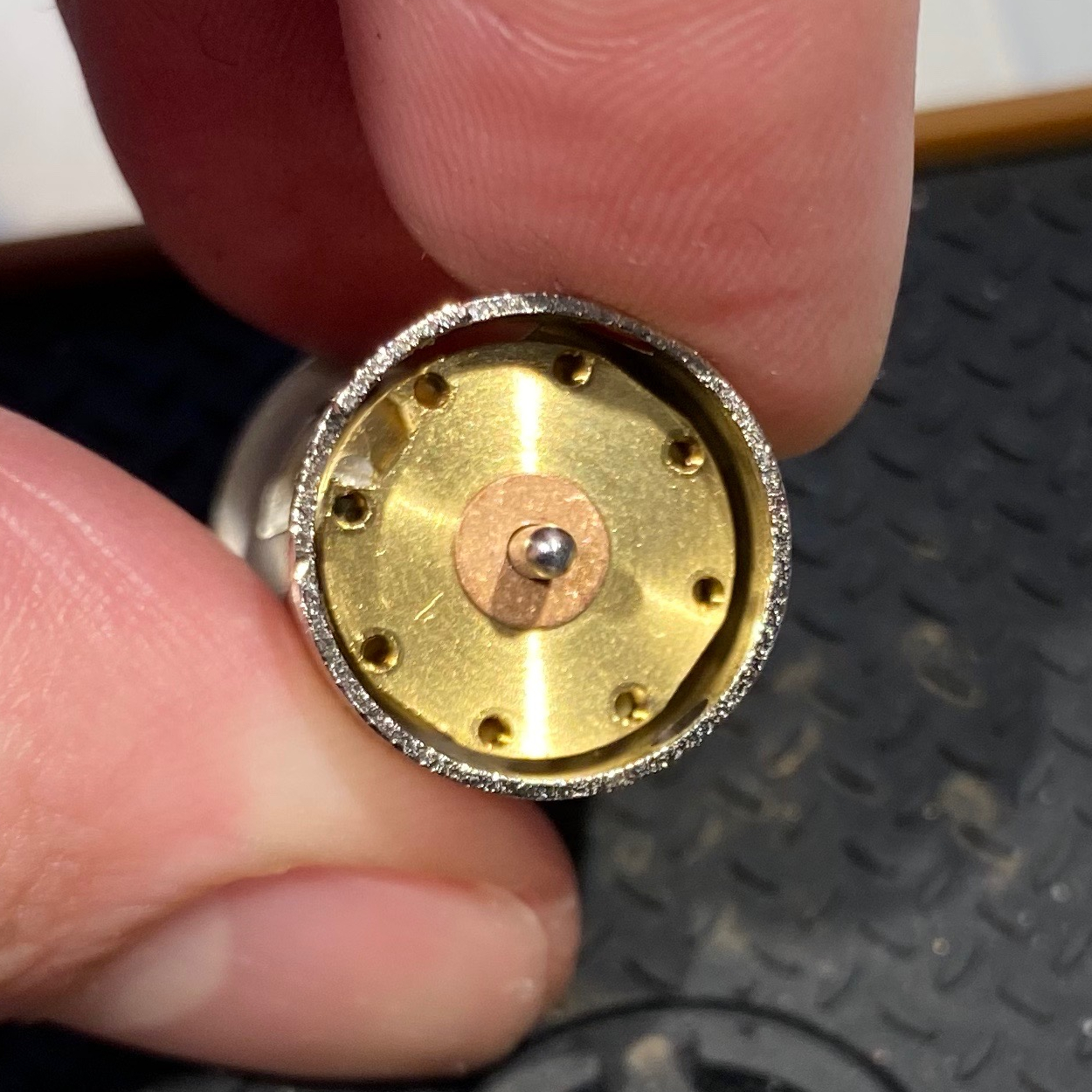
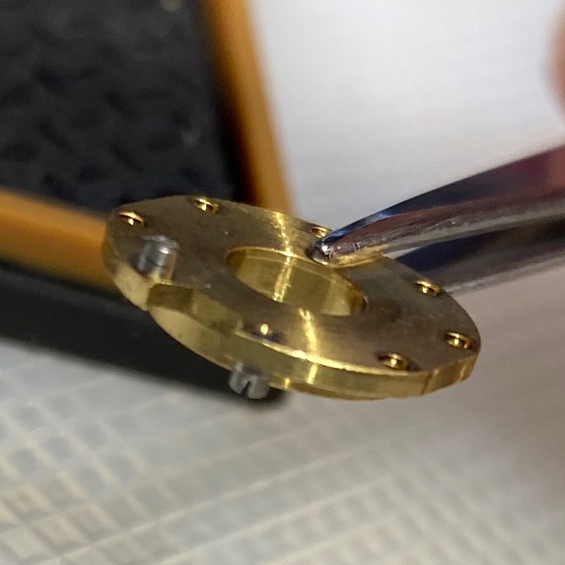
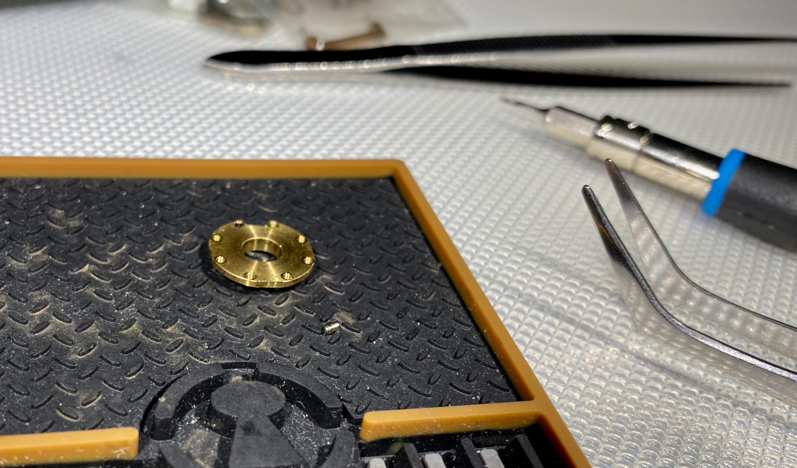
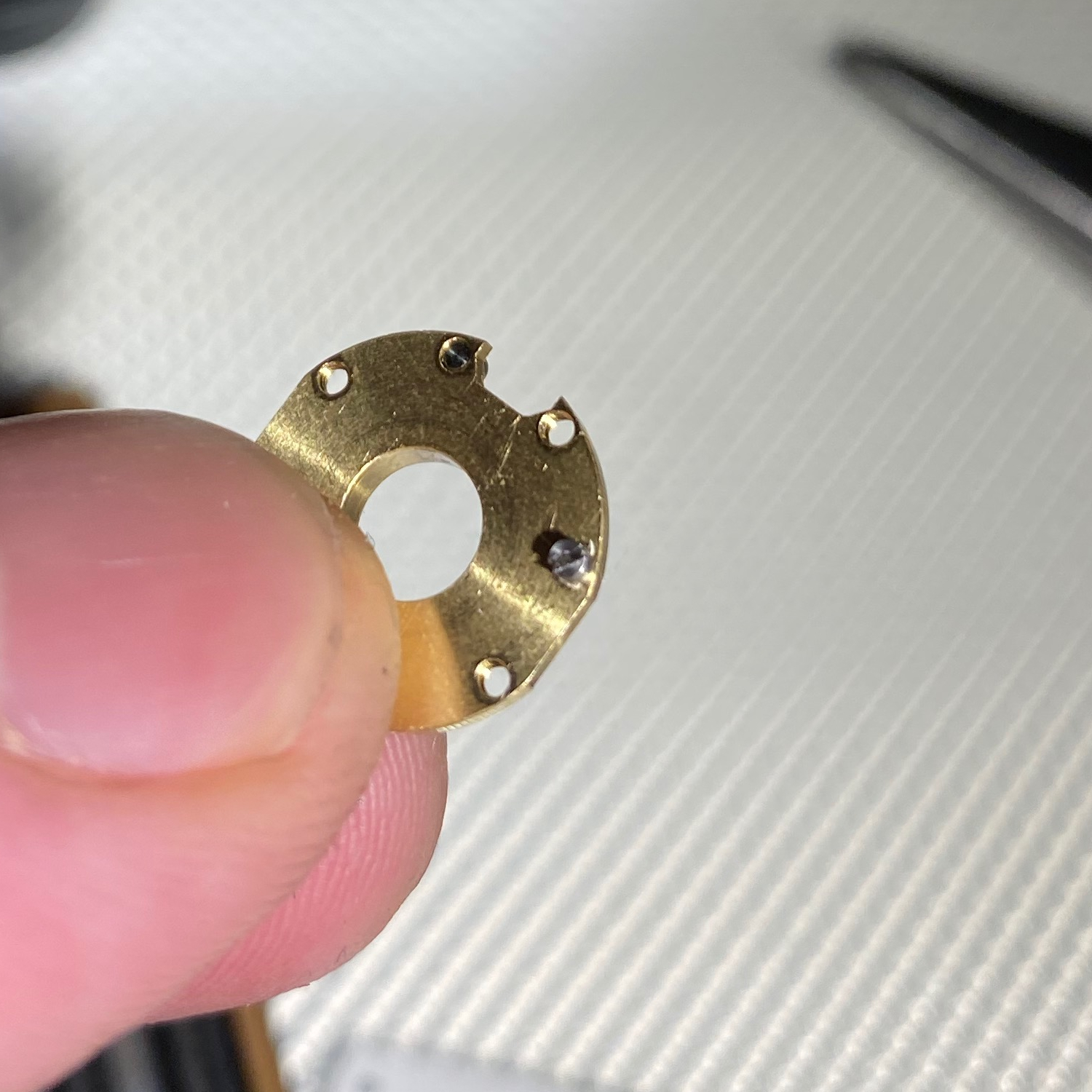
Top and under side of disks with default “0” pinning. Each disk’s three false gates are a bit poorly visible in this picture, but all gates are 90° from each other.
Figuring out a manipulation method
To even get started I had to slightly modify the dialer; normally it clicks in place to number increments, but that would stop me from getting useful feedback. I removed the screw that does this, meaning I got a free-spinning dial. Unfortunately that made accurate dialing very hard since the dial moves if you so much as look at it wrong.
My initial thought was to approach the RKS like a DD lock; I first turned all disks left or counterclockwise (“ADL”, i.e. same as AWL or all wheels left for regular combination locks) to L0, then started to apply tension while turning the dial to the right, feeling for gates on d5 passing under the sidebar. However, this method has some fairly obvious problems. First of all, you get feedback from the gates (false or otherwise) of every disk that’s rotating, including the drive disk. Even on d5 you’ve got the drive disk gates and d5’s own gates in play, and it only gets worse the further down the disk pack you go. I did feel the gates (true & false) on d5, and while I thought I could distinguish false ones from the true but that seems to have just been confirmation bias.
Like with safe combination locks, some disks are also “shadowed” by others due to manufacturing tolerances, meaning that a very slightly bigger disk (or one that sits slightly higher on the drive shaft) will block feedback from smaller disks. This means that simply turning all disks in one direction won’t necessarily give you the gate positions on all disks.
So, obviously this wasn’t a viable manipulation method, at least by itself.
“Well, it’s sort of like a safe lock?”
Maybe I should have approached it more like a safe lock?
My reasoning was that when there’s a gate under the sidebar, applying tension with the drive disk gate (think “cam gate”) also under the sidebar should allow the sidebar to descend slightly lower than otherwise, meaning I should be able to measure the width of the area where the sidebar doesn’t bind near the drive disk gate when I apply torque to the dialer’s edges to make the sidebar drop down – this is the RKS’s equivalent of the contact area and contact points you deal with on safe combination locks.
Unsurprisingly this method turned out to be the proverbial ticket, but to actually get good results I had to refine it. I had problems with consistent torque when tensioning, poor choice of initial disk positions when starting graphs, slop / play in the dial, and the sheer amount of dialing that would have to be done unless I cut down on the number of measurements I had to do.
Tensioning
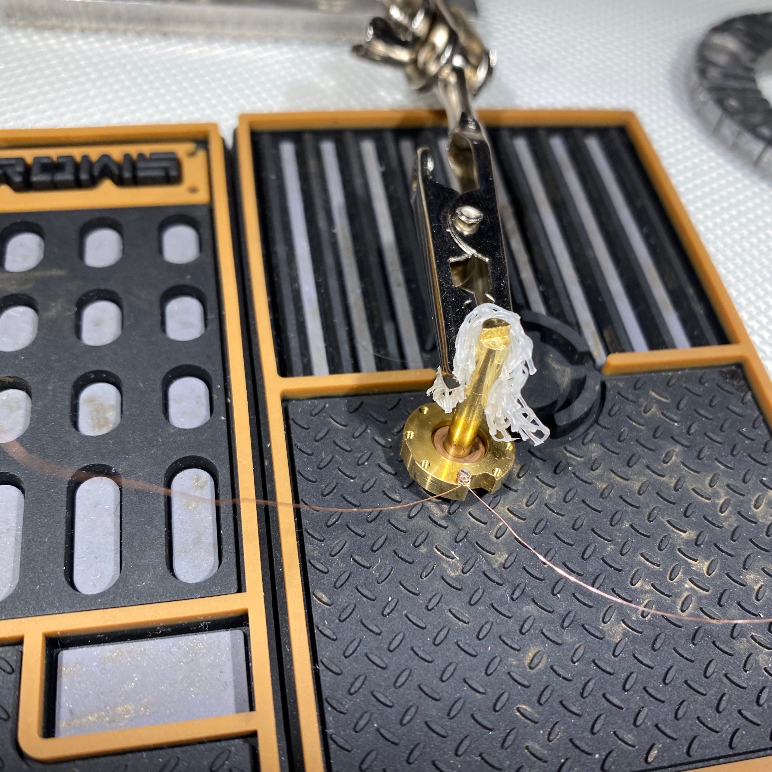
Getting consistent readings was hard since I was tensioning using my fingers – the torque I was applying was variable, which meant that the sidebar lowered different amounts every time I took measurements. So to even get started I needed to come up with a way to provide consistent torque when tensioning, and I experimented with a few different methods. Since this is a proof of concept I eventually gave up and ended up cheating a bit and tensioning by hanging some weight from the cam itself, but something similar-ish should be doable on the dialer side albeit with more work.

Tensioner attachment on the cam.
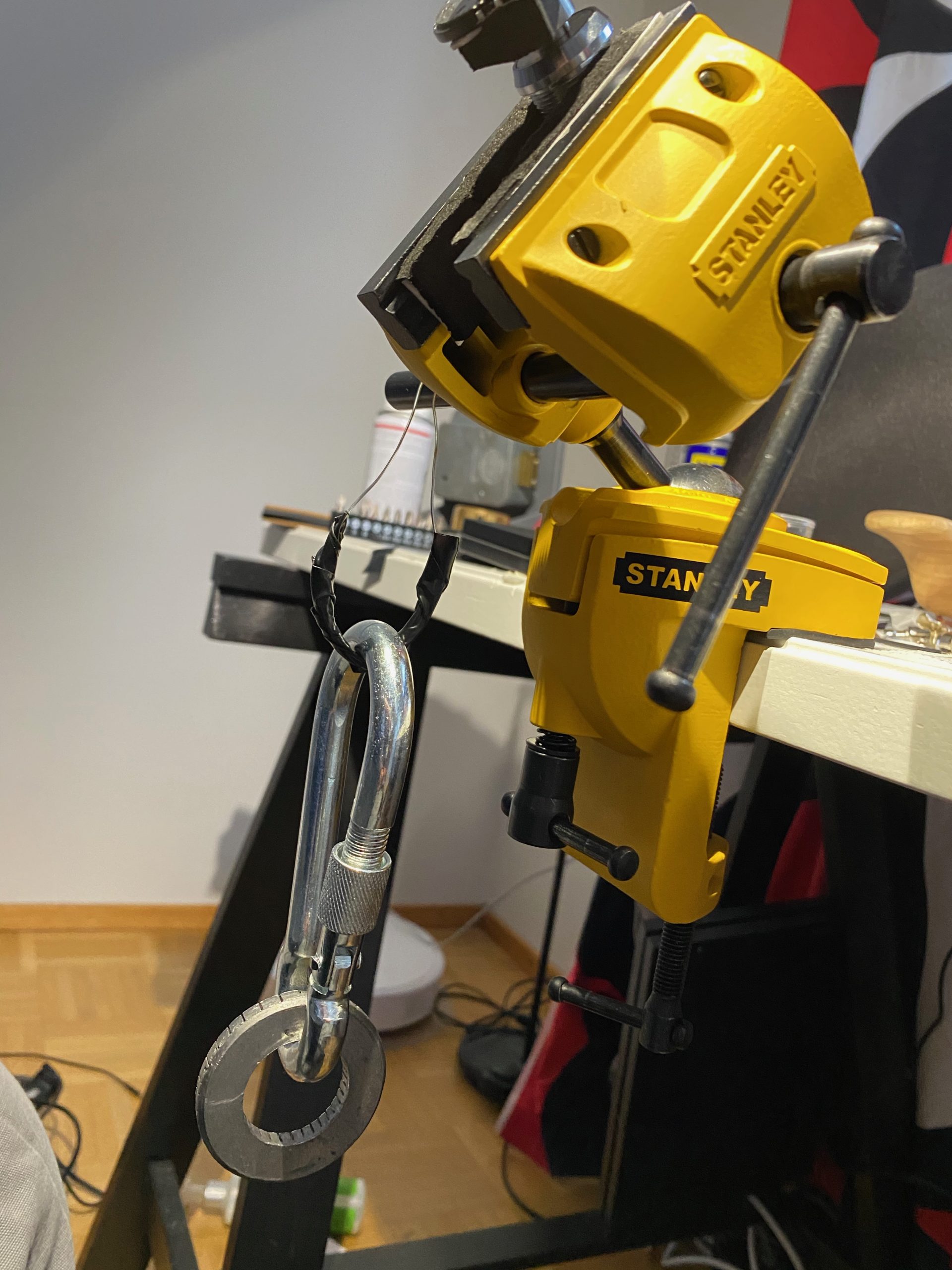
Tensioner weight (and yes that’s a Manifoil lead shield)
Initial disk positions
I started my first graphs with ADL. However I soon realized why this is a bad idea.
When going ADL, the drive pin of the previous disk ends up in the gate, meaning that it blocks the sidebar from descending and therefore gives you much narrower and shallower gate signatures.

Going ADR leaves the gates open.
Dialing
Dialing with a modified free-spinning manual dialer is extremely fiddly and liable to drive you insane, and since there’s 5 disks the amount of dialing that would have to be done with a “naïve” approach would be ridiculous.
However, the fact that gates are always 90° apart can be exploited to radically cut down on the amount of dialing. This means that when you find one position where the drive disk doesn’t bind, you know that the other gates are n * 16 increments (1 <= n <= 3) apart from it. Since gates can be felt over about 6 increments, you can then map out the edges of one gate and therefore figure out the edges of all gates.
Also, as I went along it turned out that I was getting indications in order starting from d5; my assumption is that this was due to the fact that I was tensioning the lock from the rear which meant that the sidebar would be at a very slight angle so that it’s lower on the d5 end and higher on the d1 end. After some playing around I noted the same phenomenon but reversed if I tensioned using the dialer (like it would “really” be done), so d1 would read first, then d2 and so on. This meant that once you successfully find the position of a disk’s gate you can figure out how many increments from that position the next disk’s gate will be at a minimum, and start your next graph from that position so you wouldn’t waste time graphing a spot where it’s impossible to have a gate. You can do this by using the fact that there’s a fixed amount of drive pin positions; when going right the minimum distance is - (pin distance + pin width * 2) , and left is pin distance - pin width, both modulo 64 (proof is left as an exercise to the reader).
Graphs
Graphs for this method end up looking slightly different from safe combination locks since a lot of the time you’re not actually getting any binding on the drive disk due to shadowing, so for some indices you can’t get any contact point readings.
I generally kept the cutaway “window” covered, but since this was a proof of concept I occasionally peeked to verify theories or make sure I dialed a number right.
I’ll showcase the graphs for the first 3 disks here since they’re the most interesting.
ADL
As I said, I started off with ADL before realizing it’s a bad idea. This is what the first graph where I used the tensioning tool but with ADL looked like (left contact on the bottom):
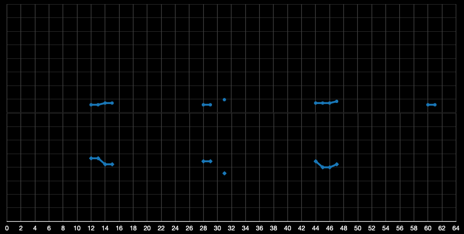
So I found the gates, but I couldn’t tell the true gate apart from the false ones.
First ADR, disk 5
Switching to ADR gave this graph. Note that only 3 gates are visible; one of them was shadowed entirely by a disk further down the pack.
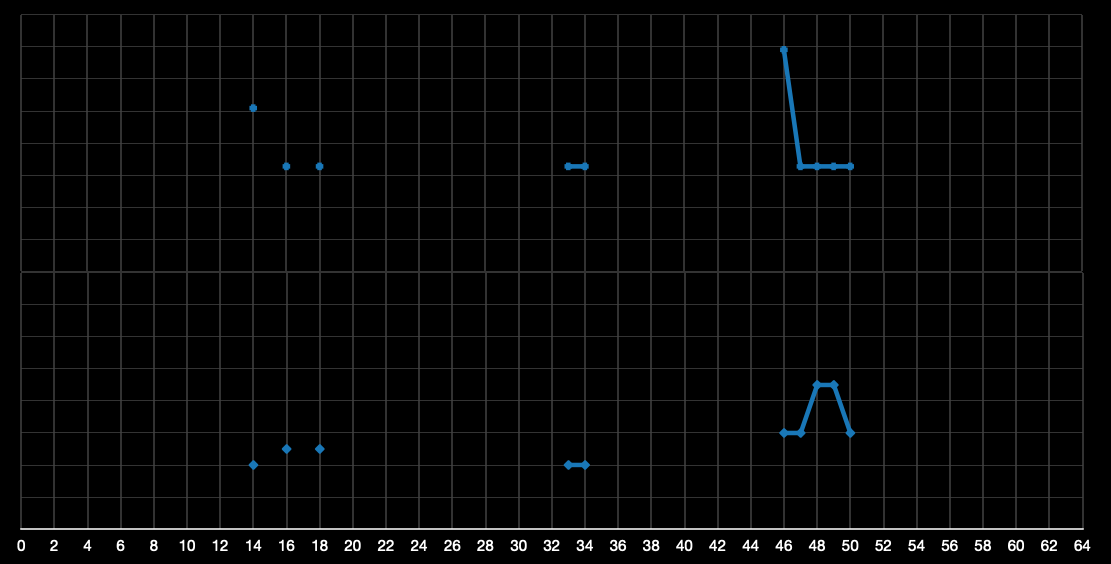
The gate with midpoint R49 gave the deepest reading with the sharpest edges. My theory was that since the false gates are so shallow, that’d be the true gate on some disk. I used my Mk I Eyeball on the cutaway window and noted that it was the gate for d5, so now I could be fairly confident that I should be able to tell the true gate apart from the false ones.
To actually verify this, I started by moving d5 a bit to the left and checked for sidebar binding. After I got worse binding for that, I did the same for d4 and got good binding, then d3 and still got good binding (ie. I essentially did a lo test but with only 3 disks). This satisfied me that I’d probably found the number for d5: R49 / L46
Disk 4
I started the next graph assuming that I’d probably be getting indications from d4, so I dialed d5 to L46 and then the rest to R38 which should be close to the first possible index for the true gate on d4.
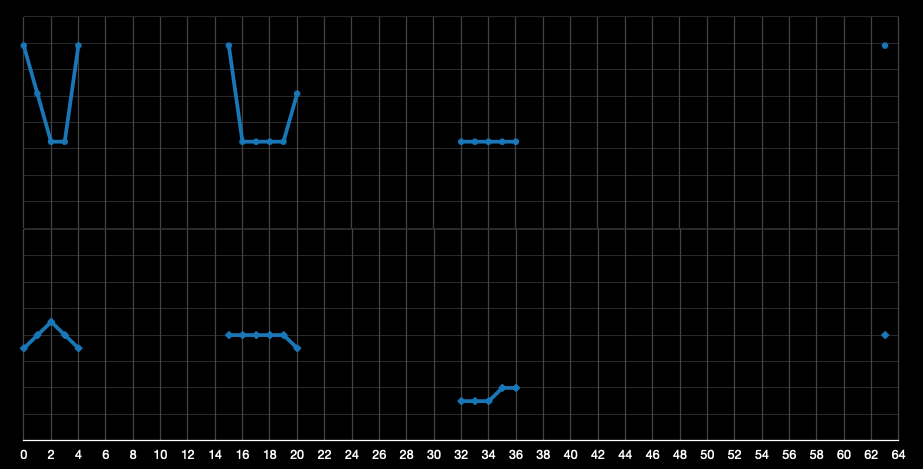
Note that gate edges are about 2 increments – ie. drive pin width – off from the gates on d5: there’s a gate edge at R20 here but it’s R18 on d5, there’s a gate edge at R36 here but R34 on d5 etc. This means that this graph is most likely for d4.
The gate with midpoint R2 has the sharpest profile, so I assume that’s the true gate. I do a lo test with just d4 and get worse results, so I figure that my assumption about this being d4 was right.
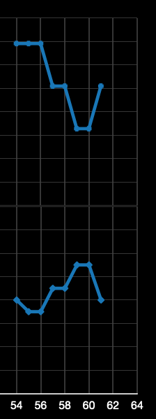
Disk 4 rotational conversion
I initially tried doing rotational conversion with my estimation of the drive pin width plus some simple math, but I kept having problems with it so I end up doing it with graphs. This is what the graph looked like for d4 R2, determining the gate midpoint is at L59:
Lucky disk 3
After finding the gate for d4, I dialed d5 @ R49, d4 @ L59, and the rest ADR to R60 which would be the first possible index for the gate on d3:
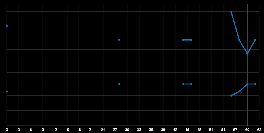
After measuring a few points around R60 I realized I probably hit the true gate right off the bat since the gate signature was so sharp and deep. I took readings from the midpoints of all the other gates and noted that they weren’t as deep as the one at R60, and after a quick lo test I declared d3 to be R60.
Disks 2 and 1 held no surprises and graphed as the first 3 had.
Et voilà, that’s how you manipulate an RKS.